Types of Sight Glasses
The term "sight glass" can refer to several types of units that allow observation of a process fluid or a feature inside of a pipe, tank or vessel. The following are the descriptions of units that are commonly referred to as sight glasses.
Liquid Level Gauge ("sight glass" in old boiler terminology)
A liquid level gauge is an instrument that is used to monitor the fluid level in a tank or vessel. In old boiler related jargon, this unit had traditionally been referred to as sight glass. Currently, it is typically referred to as a liquid level gauge, a much more descriptive label.
Figure 1 (below) shows a typical see-through liquid level gauge. This is a common configuration, intended show the liquid level only. Since this level gauge has glass on two opposing sides, lights are sometimes mounted on the "back" side to help the viewer see the level. Obviously, this instrument is not intended for observing the interior of the vessel on which it is mounted. Therefore, it is possible to simplify the viewing arrangements by using a single sided unit with a slotted "reflex" gauge glass. This type of glass features slots that effectively enhance the differences in refractive indices between liquid and gas above it, making the identification of the gas/liquid boundary much easier in the absence of other lighting arrangements.
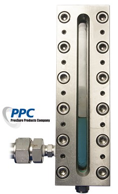
Figure 1: See-Through
Liquid Level Gauge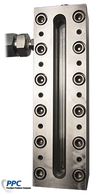
Figure 2: Reflex Glass Gauge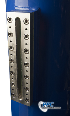
Figure 3: Vessel Mounted Level Gauge |
Sometimes, it is advantageous to be able to inspect the interior of the tank or vessel onto which the sight glass is mounted. Figure 3 shows such an arrangement. Of course, it is entirely possible to mount a wider glass piece in order to gain a much better view of the interior, and these types of oblong sight glasses, as shown in Figure 4, are also common. Production processes that include solid contents are more common than most people realize, and visual inspection through oblong sight glasses is one of the few methods for reliably assessing the quantity of solid matter in a process tank. Note again that referring to liquid level gauge as sight glasses is an obsolete practice; modern industrial sight glasses are used to observe many features besides liquid levels, and are very often used in liquid-free processes.
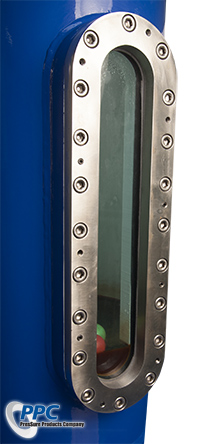
Figure 4: Oblong Sight Glass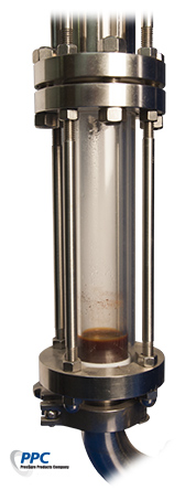
Figure 5: A Fullview Sight Glass
Configured As Level Gauge |
Sight Flow Indicator
A Sight Flow Indicator is a type of sight glass designed to allow the observation of fluids moving through a pipe. The phrase 'flow indicator' is obviously a statement of the unit' s function, and this function can be fulfilled by a few common designs.
Figure 5 shows a configuration typically called "fullview." A tubular glass is held between two flanges by long threaded rods. This type allows visual inspection from any perspective. The weakness of this type of design is that they are inherently limited to tensile strength of the tubular glass, which means that this type is not ideal for high pressures. Tubular glass is not available in very many thickness options, and larger sizes tend to be limited to relatively low maximum pressures. Note that this configuration can be used as a level gauge or a flow indicator, depending on how it is placed.
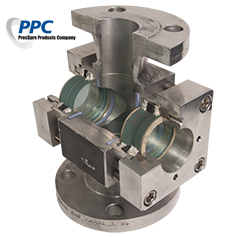
Figure 6: Cutaway of a Sight Flow Indicator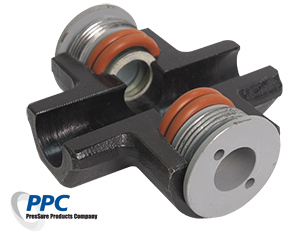
Figure 7: Cutaway of a Bull's Eye Flow Indicator. |
If higher pressures or temperatures are needed, the most common solution is to use a cross flange, and mount high pressure circular sight windows on opposite sides. Figure 6 shows such a unit. Because planar glass is available in much greater range of thicknesses, planar sight windows can be made to bear much more pressure than tubular glasses, as long as appropriate sealing configuration is used. And since the stress bearing capacity of a planar structure is a function of the square of the ratio of the piece thickness to its diameter, reducing the glass diameter can make for very high pressure flow indicators. Figure 7 shows the cutaway of such a unit, generally called "bull's eye" flow indicator. These tend to be the highest pressure rated sight glasses available.
One interesting side note is that if the flow indicator is completely filled with a homogeneous fluid, it is impossible to tell if the fluid is flowing or stationary. Therefore, it is common practice to include a moving piece whose motion would indicate flow. Various impeller and flappers are popular for this role. An example is shown as Figure 8.
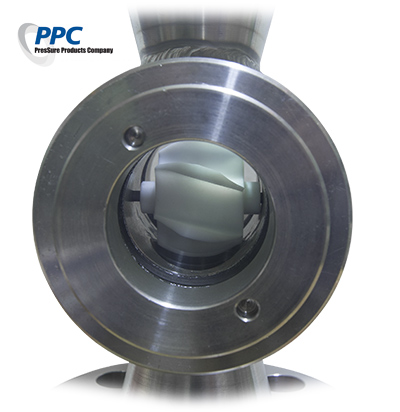
Figure 8: Flow Indicating Impeller.
Circular (Flange, Weld In, etc.) Sight Window
When the purpose of the opening is to inspect the interior of a process vessel rather than just to verify a liquid level, an elongated or oblong window shape is hardly ideal. Typical general purpose sight windows are circular. Distribution of stresses from pressure onto homogeneous materials result in most even stress profiles when pressure bearing geometries are circular. This gives rise to the fact that virtually all pressure bearing vessels from gas cylinders to aircraft fuselages have a circular cross section. Likewise, industry standard piping components are all of circular cross sections.
The typical pressure bearing industrial sight glass looks like a port window on a ship, and is installed directly onto the sidewalls of tanks and vessels to allow its interior and contents to be visually inspected. Obviously, an opening must be present on the pressure bearing shell of the tank, pipe, or vessel that will host the window. Most common of such openings are industry standard flanges - ANSI size flanges, for example - and reinforcing pads that have been welded onto the opening to compensate for the loss of structural strength caused by the opening; this reinforcement essentially decouples the attached sight glass from flexing with the pressure shell. Highest pressure sight glasses are almost universally circular.
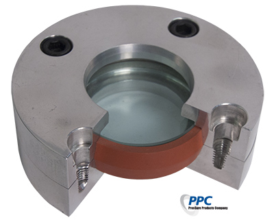
Figure 9: Cutaway of a Side-wall Sealed Circular Sight Window
Figure 9 shows a cutaway of a circular sight window. Sight windows can be classified according to their sealing mechanisms. The more common, face-sealed products use glass cushioning gaskets between the glass and the metal flange as sealing members. Therefore, the thrust of the flange bolts crushes the gasket along with the glass beneath it. This common design is simple and effective, but the fact that face sealing mechanism directly applies the sealing bolt thrust onto the glass face means it is possible to destroy the glass by over-tightening the flange bolts. Still, it generally offers the lowest up front cost, and is probably the most widely used kind.
Sidewall sealed sight windows reduce or avoid the problem of crushing the glass with excessive bolt thrust by using plastic packing material along the sidewalls of the glass lens. Seal is achieved by compressing the packing along the side walls without directly applying bolt thrust onto the glass surface. This layout is slightly more complex than the more common face sealing, but is more forgiving of excessive sealing stresses.
These units are still commonly used in condensing liquid applications, which means misting and condensation on the interior surface of the window impairs visibility. Therefore, wipers and spray mechanisms for clearing the interior of the window are available from various vendors.
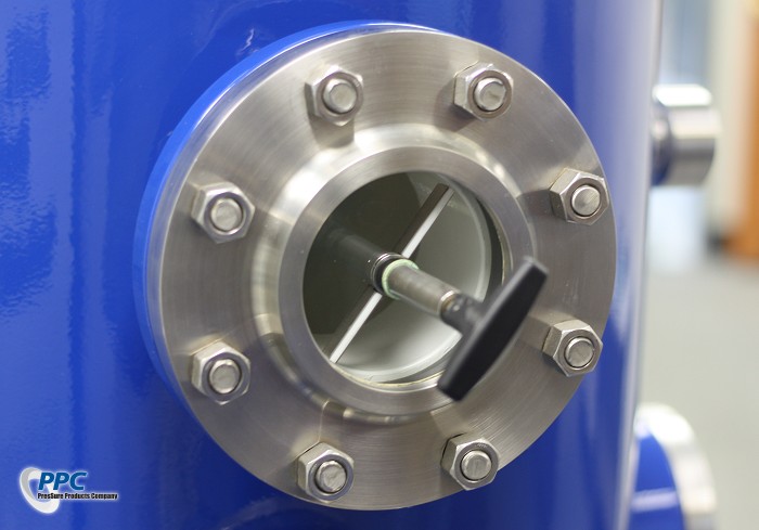
Figure 10: Wiper mounted on a circular sight glass.
Fused Sight Glass
A fused sight glass is a subset of the circular type. The main difference is that the lens and its metal ring are one discrete unit, fused together at high temperatures during manufacturing. The glass used has a much lower thermal expansion coefficient than the metal ring. After it is melted into the metal ring, the greater contraction of the metal ring imposes bulk compression on the glass. All glass failures occur in the tensile mode (and for that matter, most elastic materials fail in tensile mode). Even when the overall stress is compressive, or volume-reducing, the actual point of failure will be at the point where a tensile component develops. Therefore, placing the entire volume of glass in compression from the metal ring greatly increases the bulk strength of the glass.
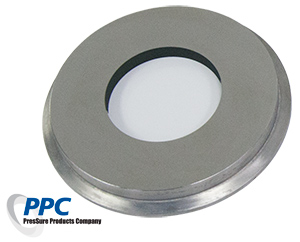
Figure 11: Sanitary Fused Glass Window
The weak point of this type of sight window is located at the surface edge of the glass, adjacent to where the glass meets the metal. Due to the fact that the lens and ring geometries are not spherical, it is impossible to impose compressive stresses without causing a tensile component to develop. This tensile component is the weak point. In fact, this tensile stress at the glass edge is one of the limiting design parameter for this type of window; if geometric parameters are not within a certain range of values, the tensile stress accumulated at the glass edge will result in a macroscopic crack.
Sometimes, these units show a crack at the glass edge. Normally, these cracks are self-arresting, and do not present a problem. However, if the process fluid is corrosive towards glass, this tensile region will be preferentially attacked; physical stress is catalytic for corrosion. In such a scenario, the stressed location would chip, and glass would shear off from the weakened area. Then the newly exposed fresh glass would corrode, and shear away again. Thus, in a corrosive medium, this type of window will degrade far more quickly than the more common kind.
While the greater bulk strength of this type is often touted by their vendors, there is not much safety advantage compared to other types; available sight windows from reputable vendors are quite safe as long as their specifications are correct.
The one genuine advantage of this type is their ease of maintenance and handling. All of the mounting and handling stresses are imposed on the metal ring rather than the glass, so probability of cracking the glass during maintenance or handling is zero. If fused glass window leaks from its flanged mount, the flange can simply be tightened down. And rough handling of the window during mounting or maintenance will not cause the glass edges to chip, as the glass edge is armored with a heavy metal ring.
| This web site is provided by: |  | Copyright 2015, All Rights Reserved. |